- Topology: V-LISN
- Frequency Range: 9 kHz – 30 MHz
- Impedance simulation: (50 µH+5 Ω) || 50 Ω
- Max. Voltage: 250 VAC 50/60 Hz, 400 VDC
- Max. Current: 4 x 50 (100*) A
- Mains terminals: 4 wing terminals
- Terminals for E.u.T.: 4 wing terminals
- Length: 480 mm
- Width: 450 mm
- Height: 370 mm
- Weight: 33 kg
- Standard: CISPR 16-1-2
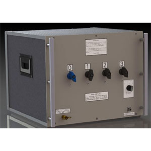
Schwarzbeck NNLK 8121 V-Line Impedance Stabilisation Network
The purpose of a LISN is to provide the device under test with energy, to carry the interference voltage to the EMI measurement receiver and to load the RF emitted by the device under test with standardized impedance.
The NNLK 8121 is equipped with a 250 µH choke as well as with a 50 µH choke which is connected in series for each path. The 250 µH choke provides an excellent decoupling between the power supply and the device under test starting at 9 kHz.
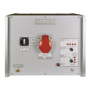
Due to high capacities very high leakage currents can occur (above 1 A). Thus it is not possible to use a residual current operated circuit breaker. It is recommended to use an isolating transformer.
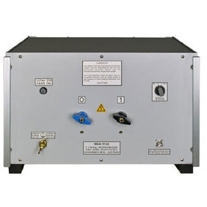
The supply voltage has to be applied at the back panel of the LISN by using the wing terminals.
The device under test has to be connected to the wing terminals at the front panel. The maximum current that can be drawn is 50 A for each path. The maximum voltage that can be applied is 250 VAC or 400 VDC. For a short period of time 100 A may be drawn from the LISN. If you want to use more than 50 A regularly, consider buying the options “high current” and “fans”, then 100 A may be drawn continuously.
")
Prodotti correlati
-
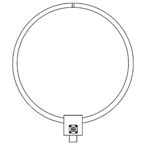 Loop - Passive
Schwarzbeck HFRA 1356 Passive Loop Antenna
-
 Line Impedance Stabilization Networks (LISN)
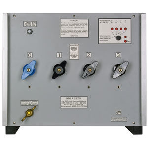
Schwarzbeck NSLK 8128 V-Line Impedance Stabilisation Network
-
 Line Impedance Stabilization Networks (LISN)
Schwarzbeck NSLK 8129 V-Line Impedance Stabilisation Network
-
 Line Impedance Stabilization Networks (LISN)
Schwarzbeck NSLK 8122 Line Impedance Stabilisation Network