- For use with one unscreened balanced pairs
- Refers schematic circuit example in CISPR 22/32 Figure D.1/G.1
- Intended for connection to cable category 3 and 5
- Changeable pin-arrangements with RJ11 and RJ45
- Can be used as CDN for IEC/EN 61000-4-6 immunity tests
- Frequency range: 150 kHz to 80 MHz
- Line parameters: 1 pair
- Power rating (EUT- and AE Port):
-
- AC max. voltage (line to ground): 63 V
- DC max. voltage (line to ground): 100 V
- Current max: 600 mA
- Test voltage: 200 VDC, 2 s
-
- Common mode impedance (EUT Port)
-
- 150 kHz to 30 MHz: 150 Ω ±20 Ω
- 30 MHz to 80 MHz: 150 Ω ±40 Ω
-


Coupling Decoupling Networks, Impedance Stabilization Networks (ISN)
")
 Richiedi Informazioni
Teseq ISN T2 Impedance Stabilization Network
Impedance Stabilization Network (ISN) for Unscreened Balanced Pairs
Impedance stabilization networks (ISN, or with CISPR 16-1-2 called AAN: asymmetric artificial network) are defined for measuring of conducted common mode disturbances at information technology equipment (ITE) as required in CISPR 22 and CISPR 32. The ISN is placed between the equipment under test (EUT) and auxiliary equipment (AE) or load which are necessary for the operation of the EUT.
The ISN establishes the common-mode termination impedance for the EUT’s telecommunications port during measurement and emulates the unsymmetrical contribution (longitudinal conversion loss, LCL) of the connected line. Different ISNs are available in relation to the line category, line numbers and pin-arrangement.
The ISN T2A is designed for measurements on one unscreened balanced pair and consists of one basic network (ISN T200A) with D sub 25 connectors and special adapter sets. A set of adapters consists of LCL adapters to realize the longitudinal conversion loss (LCL)- requirements for the EUT-side in relation to the used cable category (cat. 3, cat. 5) and a connection adapter for the AE-side.
Ti potrebbe interessare…
-
 Coupling Decoupling Networks
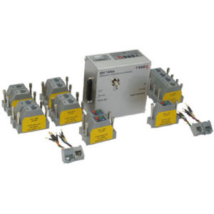
Teseq ISN T4 Impedance Stabilization Network
-
 Coupling Decoupling Networks
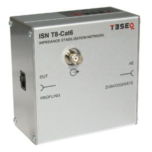
Teseq ISN T8-Cat6 Impedance Stabilization Network
-
 Coupling Decoupling Networks
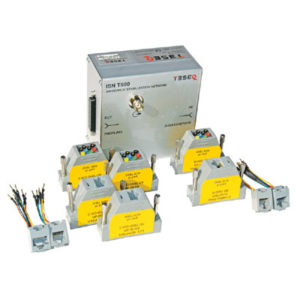
Teseq ISN T8 Impedance Stabilization Network
Prodotti correlati
-
 Coupling Decoupling Networks
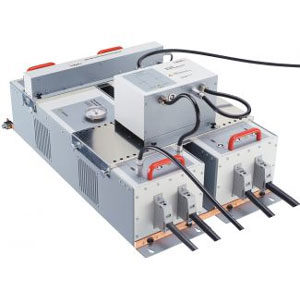
Teseq CDN 3083-S100 Manual Surge Coupling / Decoupling Network
-
 Coupling Decoupling Networks
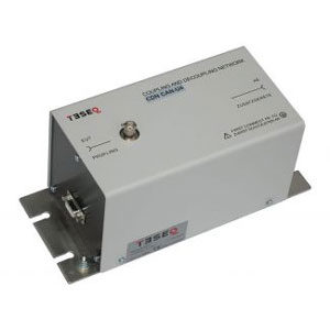
Teseq CDN CAN-U5 Coupling / Decoupling Network
-
 Coupling Decoupling Networks
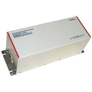
Teseq CDND Coupling / Decoupling Network Series
-
 Coupling Decoupling Networks
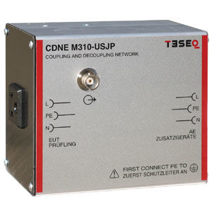
Teseq CDNE M310-USJP Coupling / Decoupling Network for Emission Measurement